
The seminar, “Robotics for Everyone”, had as its primary goal to introduce teachers to robotics so that more schools across the Philadelphia School District would develop robotics programs: the ultimate goal being to prepare students for 21st century jobs in Science, Technology, Engineering and Math (STEM). This unit includes lessons which provide students with an opportunity to experience STEM within a classroom setting in order the create excitement for the pursuit of higher learning and careers in these subjects. To accomplish the objectives, students will experience STEM by: building circuits on a breadboard and programing an Arduino microcontroller, applying trigonometric definitions to a Ferris wheel, building a Ferris wheel, and designing and building a robot arm which they ultimately can program.
This is a critical time for attracting racial and ethnic minorities to STEM careers. According to U. S. Census Bureau projections, racial and ethnic minorities are expected to comprise more than half of the national population by 2050. This demographic shift means that minority students will make up an increasingly larger percentage of students in the national education system and STEM talent pool. Yet, relatively low rates of success among minority students in STEM education persist. Thus, maximizing exposure and preparation become essential to future STEM representation. This curriculum unit has been written for use in a high school Mathematics classroom but is also appropriate for engineering technology, career technology courses and robotics classes or clubs.
The seminar, “Robotics for Everyone”, had as its primary goal to introduce teachers to robotics so that more schools across the Philadelphia School District would develop robotics programs: the ultimate goal being to prepare students for 21st century jobs in Science, Technology, Engineering and Math (STEM). The need for skilled workers in STEM careers is expected to skyrocket over the next fifteen years as baby-boomers retire and technology continues to advance at astonishing rates. This trend in addition to lower educational budgets and more focus on new Common Core standards creates an opportunity to integrate STEM into the everyday classroom. Robotics is unique in its content as it encompasses all of the STEM areas. Within the student population of urban cities like Philadelphia, as the public school population shifts to proportionately more racial and ethnic minorities, the importance of STEM education among this underserved population becomes that much more important for new employees in the STEM marketplace Increasing the success of racial and ethnic minority students in science, technology, engineering and mathematics has become a critical issue. Indeed, several trends underscore the importance of fostering success among minority students in STEM education. According to the U. S. Census Bureau projections, racial and ethnic minorities are expected to comprise more than half of the national population by 2050. This demographic shift means that minority students will make up an increasingly larger percentage of students in the national education system and STEM talent pool. Yet, relatively low rates of success among minority students in STEM education persist. Thus, understanding how to maximize success among racial and ethnic minorities in STEM education is even more critical. (Museus etal, 2011). In addition, increasingly, students entering institutions of higher education are required to have more advanced prerequisite skills as technology advances and the material needed to compete in our global economy increases. For minority students the road to STEM is more arduous. Existing evidence indicates that several factors may significantly influence the success of racial and ethnic minority students in STEM. At the K-12 level, scholars have underscored the critical linkage between under preparedness and a lack of success in STEM education (Museus, Palmer, and Davis 2011). The Robotics for Everyone seminar taught the key scientific areas of electronics, physics, math, computer science, technology and engineering and applied the “principles and practices of robotics”. It was a hands-on course which expanded participants’ knowledge of applied science through microprocessor programming critical to STEM education. The course used the Arduino open source microcontroller to learn control systems basics and computer programming. (Arduino, 2014) The project based aspects of this course lends itself well to the inner city students we teach. These students are frequently visual, kinesthetic learners who need to both see the lesson and also experience it. This unit will help enrich their learning experience by providing lessons which have a purpose and teach by doing. Hand-on educational projects are the constructivist’s answer to the learner creating their own knowledge. This unit will take the “maker approach” to educational concepts and allow students to create using the creative decision making process known as the engineering process. The maker movement follows the long held premise that “learning by doing” creates long-term knowledge. John Dewey wrote, “The school must represent present life—life as real and vital to the child as that which he carries on in the home, in the neighborhood, or on the playground.” He also wrote that “education is not preparation for life; education is life itself.” These ideas are just are true today and can be realized through hands-on, project based learning and “making”. With the launch of MAKE Magazine in 2005, Dougherty and his team provided the catalyst for a tech-influenced DIY community that has come to be identified as the Maker Movement. (Make Magazine). Many makers are hobbyists, enthusiasts or students (amateurs!)–but they are also a wellspring of innovation, creating new products and producing value in the community. Some makers do become entrepreneurs and start companies. (Martinez, Stager 2013) As the movement has gathered increasing momentum, makers have created their own market ecosystem, developing new products and services. The combination of ingenious makers and innovative technologies such as the Arduino microcontroller and personal 3D printing are driving innovation in manufacturing, engineering, industrial design, hardware technology and education. Over the years, the MAKE division has become synonymous with the Maker Movement and is the recognized leader of this growing community of makers. (Makemedia) The maker movement as it is called is moving swiftly into classrooms. Sylvia Martinez and Gary Stager write, in Invent to Learn, a book that some call the “Maker in Education bible”, “Maker classrooms are active classrooms. In active classrooms one will find engaged students, often working on multiple projects simultaneously, and teachers unafraid of relinquishing their authoritarian role. The best way to activate your classroom is for your classroom to make something” (Martinez, Stager 2013). Much as STEM education through a robotics club where participants create a robot from scratch to meet the demands of competition rules, student lessons of this unit will teach core concepts and this allow students to envision their final project based on their creative design and critical thinking in a classroom. Once the product is designed, students will make and revise their product to achieve the task outlined. The engineering design process is important to make certain students are using a methodical process while they “tinker”. The engineering design process is a series of steps that engineers follow when they are trying to solve a problem and design a solution for something; it is a methodical approach to problem solving. This is similar to the “Scientific Method” which is taught to young scientists.(Teach Engineering). The simplest form of the engineering design process begins with an idea to solve a problem, the idea is tested and then evaluated. The middle and last step can be repeated over and over as product improvement, new ideas and product refinement happens. This cycle and repetition is why it can be said that design is an iterative process. (Vex Robotics)) In this unit high school students enrolled in algebra courses whose content includes trigonometric functions can engage in a project based learning experience including the STEM disciplines. The mathematical connections and engineering principles for arms and grippers can be modeled using trigonometry. Students can connect the real-life application of trig ratios, motion and final placement with trigonometric functions. Computer programming introduces logic and computer language algorithms within a practical application. The unit circle, and angle rotations are often introduced as abstract concepts. This unit will help students visualize movement around the unit circle using a Ferris wheel constructed by students.

The objective of the seminar, Robotics for Everyone!, was to expose teachers to the principles and practice of robotics so that teachers could take basic robotics principles back to their classrooms and build simple robots with students. The objective of this unit is to provide students with an opportunity to experience STEM within a classroom setting in order the create excitement for the pursuit of higher learning in science, technology engineering and math. Racial and ethnic students are underrepresented in STEM fields both because they don’t seek to enter the field, find they aren’t prepared to pursue a degree in the field or they leave the field shortly after taking positions in STEM careers. (Palmer, etal 2011). The opportunities to expose students to STEM will increase their interest and create opportunities to plant new seeds of interest. This unit allows for an experience both around topics they are studying in their classes and computer programming which they might never encounter in a traditional classroom setting. Students frequently cannot see any connections between school and the real world. This exposure should help make education more relevant.
To accomplish the objectives, students will experience STEM by:
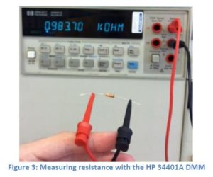
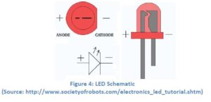
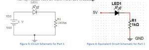
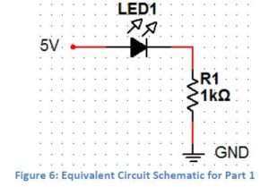
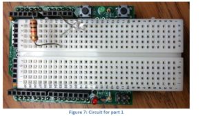
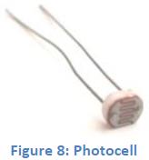
There are three lessons in this unit: 1.) Introduction to Circuits and the Arduino, 2.) Reinventing the Wheel and 3.) Placement of a Swinging Robotic Arm. Learning Objectives: Students will: Materials The first lesson is an extended lab exercise. After students learn about the flow of electric current, Ohms law and voltage they can apply the knowledge in the lab. The center piece of this hands-on lesson is the Arduino microcontroller. The Arduino, when fitted with a protoshield or breadboard onto which simple circuits have been added, can be programmed to complete a variety of tasks. Students will learn to build a circuit on the breadboard and measure its voltage with a Digital Millimeter (DMM). When the circuit is established the LED light comes on signifying the flow of electricity. A photo resistor and potentiometer are added to the breadboard to act as light sensor and to change the output of an action in the system. Next students will learn to vary the signal of the LED using computer programming. There are many free resources for computer software on the internet. The lab instructions provide “C+ language” code which will make the LED blink and stop. Students will copy the code provided into the computer program and download it using a USB cable to the Arduino. The code is written to adjust the potentiometer to regulate how often and how long the LED lights. (See appendix for lab instructions and details). Learning Objectives: Students will demonstrate an understanding of trigonometric functions when applied to a Ferris wheel Students will: Materials: The second lesson requires students to utilize their knowledge of trigonometry to graph the sine function of the motion of a Ferris wheel, determine the coordinates of different locations and to build a Ferris wheel of their own design to within given satisfy constraints. Prior to the first activity, students will learn to solve for acute angles in right triangle problems using trigonometric ratios. They will also use the inverse trigonometric functions to find the lengths of triangle side lengths. Students will use these skills to complete the first portfolio lesson, finding the coordinates of the designated points and distances on the Ferris wheel. For the next portfolio lesson, students will use their knowledge of angle rotations to complete the questions and graphs. These questions use the ground as the point of reference rather than the middle as in the previous problem. The graphic representation will reflect those differences. The third activity introduces time to the Ferris wheel problem so that students can begin to think of the mathematics of motion. This is valuable given trigonometric functions often describe things that are moving (particles, sound, etc.). Students will utilize their knowledge of the unit circle to complete the activity and apply it to a real world problem. The independent project asks students to design a Ferris wheel which will allow Philadelphians to enjoy the center city skyline from the school yard (which sits at a high elevation). Students will need to conduct research in order to determine the height needed for the Ferris wheel (based in part on the height of the hill) and the speed it should go to allow people to take pictures. The last project allows students to be “makers” with the freedom of design as well as to use critical thinking skills to make decisions about building their own Ferris wheel. Students will use the engineering design process to guide their design. An extra problem using trigonometry and gears is provided as extra credit. The Ferris wheel uses gears for movement so for students who are interested, this relevant problem using trigonometry is provided. Learning Objectives: To apply trigonometric calculations to real life situations Students will: Materials: The final lesson, lesson three, allows students to consider angle rotation, and coordinates along the unit circle to determine how far a robotic arm swings given information in a problem. Once students understand the essence of the problem, they build a robotic arm and if the Arduinos are available program it to stop at the prescribed location. This calculation is the type of activity engineers creating arms for industrial work must accomplish so that the arm moves with precision about it prescribed task. The internet has many types of robotic arms and grippers for students to research and study. The type of arm and gripper can be prescribed by the teacher or driven by tasks defined in a robotic competition.Lesson 1- Introduction to Circuits and the Arduino Robot
Lesson 2- Reinventing the Wheel
Lesson 3 – Placement of a Swinging Robotic Arm
Ampaw, Frim, and Margaret Partlo. “Racial and Ethnic Minority Students’ Success in STEM Education by Samuel D. Museus et al. (review).” The Review of Higher Education 36.4 (2013): 551-52. Web. An overview of existing knowledge regarding factors that influence success among racial and ethnic minority students in the science, technology, engineering, and mathematics (STEM) circuit. Research provides recommendations for increasing minority presence in STEM fields. Martinez, Sylvia L., and Gary S. Stager. “How the Maker Movement Is Transforming Education.” Making Matters. We Are Teachers, 5 May 2011. Web. 31 May 2014. Martinez, Sylvia Libow., and Gary Stager. Invent to Learn: Making, Tinkering, and Engineering in the Classroom. Torrance, CA: Constructing Modern Knowledge, 2013. Print. Palmer, Robert T., PhD. “A Qualitative Investigation of Factors Promoting the Retention and Persistence of Students of Color in STEM.” Journal of Negro Education. (2011): 491-504. Web. Research outlining the strategies for minority student retention in STEM Swanson, Jackie. “Simple Machines.” Http://www.nasa.gov/offices/education/programs/national/dln/events/Simple_Machines.htm. N.p., n.d. Web. 25 June 2013. Teach Engineering Resources for k-12 Resources for teaching engineering A Guide to Robotics Projects http://www.sciencebuddies.org/science-fair-projects/search.shtml?v=ia&ia=Robotics “Engineering Is Elementary.” The Engineering Design Process. N.p., n.d. Web. 31 July 2014. <http://www.eie.org/overview/engineering-design-process>. A simple engineering design process (EDP) to guide students through engineering design. “History of Robots.” Wikipedia. Wikimedia Foundation, 16 July 2014. Web. 31 July 2014. <http://en.wikipedia.org/wiki/History_of_robots>. “MAKE: Education.” MAKEzine.com. N.p., n.d. Web. 30 May 2014. <http://makezine.com/>. Davis, Vicki. “How the Maker Movement Is Moving into Classrooms.” N.p., n.d. Web. <http://www.edutopia.org/blog/maker-movement-moving-into-classrooms-vicki-davis>. Great background information on the maker movement in education “Learning by Making: American Kids Should Be Building Rockets and Robots, Not Taking Standardized Tests.” Making in Education. Maker Media, n.d. Web. 25 May 2014. <http://makermedia.com/about-us/making-in-education/>. Other: Robotics & Competition Websites Sites Arduino http://www.arduino.cc/ Everything you need to build using the Arduino microcontroller Boosting Engineering Science and Technology (BEST) website http://best.eng.auburn.edu/ Excellent, robotics competition challenge; educational competition theme, competition components strengthen 21sty century skills (writing, speaking, critical thinking) Instructables http://www.instructables.com/index Do it yourself projects; inexpensive, complete directions Marine Advanced Technology Education, http://www.marinetech.org/ Sea Perch Competition Teach Build Become, http://www.seaperch.org/index Science Buddies Website, http://www.sciencebuddies.org/science-fair-projects/project_ideas.shtml Ideas for maker projects. Teaching Engineering http://www.teachengineering.org Teacher support website The Maker Movement, Maker Faire, http://makerfaire.com/maker-movement/ website of projects, conferences, resources for maker projects in education Vex Robotics, http://vexrobotics.com/ Robotics competition site Vex Robotics http://curriculum.vexrobotics.com/curriculum/intro-to-engineering/what-is-the-engineering-design-process Robotics education and teaching resourcesTeacher Resources
Student Reading List
Classroom Materials
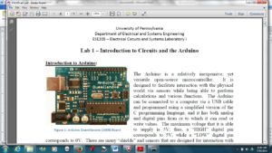
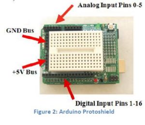
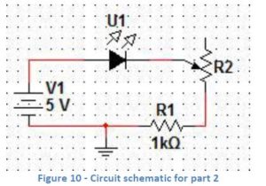
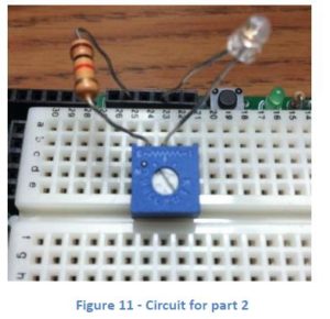
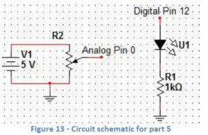
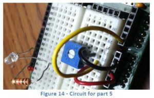
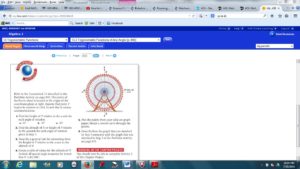
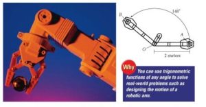
Lesson 1 Circuits and the Arduino (University of Pennsylvania Electrical Circuits and Systems Laboratory 1) http://www.seas.upenn.edu/~ese205/ Arduino Materials Lab 1 – Introduction to Circuits and the Arduino Introduction to Arduino: The Arduino is a relatively inexpensive, yet versatile open-source microcontroller. It is designed to facilitate interaction with the physical world via sensors while being able to perform calculations and various functions. The Arduino can be connected to a computer via a USB cable and programmed using a simplified version of the C programming language, and it has both analog and digital pins from or to which it can read or write values. The maximum voltage that it is able to supply is 5V; thus, a “HIGH” digital pin corresponds to 5V, while a “LOW” digital pin corresponds to 0V. There are many “shields” and sensors that are designed for interaction with the Arduino, or microcontrollers in general. The Arduino can read values from sensors or other inputs, and it can also write values to other components based on computations given by the program. Arduino is fast becoming one of the most popular microcontrollers on the market. Its ease of use, extensive software library and most importantly, its low cost (~$30 for a basic set compared to $150 for other microcontrollers) has come to make it as popular as it is today. Many projects using the Arduino can be found on www.hackaday.com. In this introductory lab, you will become familiar with the Arduino and some of its applications. First, you will learn to use a breadboard to build simple circuits. You will also apply Ohm’s Law to analyze your circuits. You will then use the Arduino to interface between hardware (your circuits) and software (the code). Procedure: ***Answer all questions on the handout to be turned in at the end of lab*** You will now build a very basic circuit on a breadboard, also called a protoboard. The breadboard shield that we are using, shown in Figure 7, features 30 rows of holes arranged in sets of five on each side of the partition. Each of the five holes in a row is electrically connected by a conducting plate running underneath. Therefore, if you were to connect a wire from 5V to a hole, anything connected to the other four holes in that row would be at a potential of 5V. – You should always put a resistor in series with an LED in order to limit the current flowing through the LED (and thereby prevent it from burning out). – Always make sure no bare wires are touching! Connect the Arduino (with the breadboard shield attached) to the computer using the USB cable. This will supply power to your circuit. Your LED should now be lit! Circuits are generally designed to accomplish some sort of fixed task, such as blinking a light or amplifying a sound signal. Often, however, you will want to add user input to your circuit, so that you can change its behavior on the fly (for example, setting the blink rate or adjusting volume). You will now examine two simple ways of controlling the behavior of your circuit. A photoresistor, sometimes called a photocell, is a form of variable resistor whose resistance decreases with exposure to light. In effect, a photoresistor is a light sensor. (See Figure 8 on right) A more common way to provide user input to a circuit is by using a potentiometer, or pot for short. You have all used a potentiometer at some point, probably to adjust the volume of some device. A potentiometer looks like this: A potentiometer is a three‐terminal device. The resistance between the two outermost terminals, R1‐3, is constant (this constant value is in fact written on the side of the potentiometer), but the center terminal (2) acts as a “wiper” that slides back and forth along the resistor as you rotate the potentiometer. Therefore, R1‐2 and R2‐3 change, but their sum R1‐2 + R2‐3 = R1‐3 is constant. Now you will upload a code to the Arduino to make an LED flash on and off. Open the Arduino IDE (see the Arduino Software Instructions document for help on using the Arduino software and uploading code). Copy the following code into the window, or go to Files à Examples à Basic à Blink: /* Blink Turns on an LED on for one second, then off for one second, repeatedly. This example code is in the public domain. */ void setup() { // initialize the digital pin as an output. // Pin 13 has an LED connected on most Arduino boards: pinMode(13, OUTPUT); } void loop() { digitalWrite(13, HIGH); // set the LED on delay(1000); // wait for a second digitalWrite(13, LOW); // set the LED off delay(1000); // wait for a second } Notice that text following two slashes // or between /* */ is grayed-out and is not read by the Arduino; these are known as “comments,” and they serve to assist the reader in understanding the code. Also note that time is specified in milliseconds. Construct the circuit shown in Figures 13 and 14. You will need to use a few jumper wires to connect the potentiometer to the pins. Copy the following code into the window and upload to the Arduino: /* Blink with variable rate Turns an LED on and off repeatedly at a rate varied by a potentiometer. */ int analogPin = 0; // analog pin used to connect the potentiometer int val; // variable used to store the value from the analog pin void setup() { pinMode(12, OUTPUT); // initialize the digital pin as an output } void loop() { val = analogRead(analogPin); //set val equal to the value read from analog pin 0 digitalWrite(12, HIGH); // set the LED on delay(val); // wait for val milliseconds digitalWrite(12, LOW); // set the LED off delay(val); // wait for val milliseconds } Keep the circuit from Figure 13 on your breadboard and upload the following code: int analogPin = 0; // analog pin used to connect the potentiometer int val; // variable used to store the value from the analog pin void setup() { pinMode(12, OUTPUT); // initialize the digital pin as an output } void loop() { val = analogRead(analogPin); if(val >= 512 && val < 1000){ digitalWrite(12, HIGH); delay(250); digitalWrite(12, LOW); delay(250); } else if(val >= 1000){ digitalWrite(12, HIGH); } Else { digitalWrite(12, LOW); } } Extra Credit: If you have time, modify your circuit and code so that the LED turns on only when you cover a photoresistor with your finger. The LED should remain off otherwise. Hint: you will need to use another resistor in your circuit to create a voltage divider: http://www.acroname.com/howto/photoresistor/photoresistor.html Show your teacher to receive your extra credit! Lesson Plan 2 Chapter Project – Reinventing the Wheel (adapted from Holt Algebra 2 Chapter Project Thirteen) Navy Pier’s visible attraction, a 150 foot Ferris wheel, is modeled after the very first Ferris wheel, which was built by George W. G. Ferris for Chicago’s 1893 World Columbian Exposition. The Navy Pier Ferris wheel offers unpatrolled views of Chicago’s skyline and lakefront. With 40 gondolas that seat 6 passengers each, the Ferris wheel can accommodate up to 240 passengers at a time. In the evening, the Ferris wheel’s 40 spokes spanning a diameter of 140 feet are illuminated by thousands of lights. The Ferris wheel takes approximately 440 seconds to make one complete revolution. Imagine that you are building a Ferris wheel on Overbrook property tall enough to view beautiful Philadelphia downtown landscape. In order to sell your idea, you are required to make a model for a presentation and d explain in mathematical terms what a viewer can see at different heights using trigonometry. As a person rides a Ferris wheel that is rotating at a constant rate, the distance between a person and the ground can be modeled by a sine function. The Ferris wheel presents a nice model of a Chapter Project Activity 3 – Using the table of values that you created in Activity 2 and the fact that one complete revolution takes 440 seconds, convert the units of the independent variable from degrees to time in seconds. Graph the points and sketch a smooth curve through the points. Then, find the linear speed in miles per hour of a rider on the Ferris wheel. Will they have time to take pictures when they get to the top? Chapter Project Activity 4 – Write an equation of the function y=a sin b to model the altitude of a rider on the Ferris wheel as function of time. Describe what each variable In your model represents. Independent Project – Based on the Cosmoclock 21 Ferris wheel questions above and New York Navy pier examples described above, design your own Ferris wheel to be placed on the Overbrook High School blacktop behind the gymnasium. Consider that this neighborhood site will boast of a beautiful view of downtown Philadelphia, so it has to be high enough to deliver on the promise of a panoramic view. Use the engineering design process to define the problem, brainstorm solutions, draw out a model, build and redesign your idea. CAD drawing software can be used from the online programs provided on classroom computers for your drawings. How does the Ferris wheel represent a model of the unit circle? Attach an enlarged copy of the unit circle to your Ferris wheel, mark the coordinates for each standard angle. Concept Extension – The Ferris wheels considered in this lesson are powered by motors and given movement using gears. Students can extend their learning by learning about gear ratios. A problem using trigonometry is found below: Source Portfolio questions: Holt Algebra 2 2003 Materials Ferris wheel construction: K’NEX Collect and Build Ferris Wheel http://www.knex.com/shop/17290/ferris-wheel/ $10.00 – also available at Walmart $22.00 Lesson 3 Building a Robotic Arm and gripper that swings to a new location to place an object Steve is programming a 2 meter long robotics arm. At the end of the arm is a gripper which grasps an object at point A, located directly to the right of the pivot point , O. The arm swings through an angle of 140° and releases the object at point B. What is the new position of the object relative to the pivot point? Solution: Place the pivot point at the origin. The new position at point B has the coordinates (r cos θ, r sin θ). Substitute 2 for r the length from the pivot point to the end of the arm at the gripper or the radius of the circle and 140° for θ. Student problem: Suppose that the length of the robotic arm is 3 meters. Find the new position of the objects after the arm swings through an angle of 200°. Maker extension: Students make a robotic arm and program it to move based on the location designated . Students should use the engineering design process to plan and implement their design.


unit circle and the sine function represents the seat’s distance from the ground as it rotates around the Ferris wheel. You will be given the dimensions of the Chicago Ferris wheel.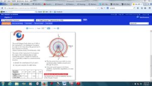
Chapter Project Activity 2 – Create a table of values for the altitude (height above the ground) of a rider on the Ferris wheel. Let the independent variable include all common angle measures for θ such that 0° ≤ θ ≤ 810°. Graph the points and sketch a smooth curve through the points.
Chapter Project Activity 1 – Using a compass and straight edge, graph a representation of the Navy Pier Ferris wheel on a coordinate plane with its center at the origin (see introduction for dimensions). Create a table of values for the distance from a point on the Ferris wheel to the x-axis. Use the following angles of counterclockwise rotation: 0°, 90°, 180°, 270°, … 810°. Graph the resulting ordered pairs and sketch a smooth curve through the points.


Standard Area 2.5 Mathematical Problem Solving and Communication 2.5.11.A: Develop a plan to analyze a problem, identify the information needed to solve the problem, carry out the plan, check whether an answer makes sense, and explain how the problem was solved in grade appropriate contexts. 2.5.11.B: Use symbols, mathematical terminology, standard notation, mathematical rules, graphing and other types of mathematical representations to communicate observations, predictions, concepts, procedures, generalizations, ideas, and results. Standard Area 2.8 Algebra and Functions 2.8.11.E: Use combinations of symbols and numbers to create expressions, equations, and inequalities in two or more variables, systems of equations and inequalities, and functional relationships that model problem situations. Standard Area 2.10 Trigonometry 2.10.11.A: Identify, create, and solve practical problems involving right triangles using the trigonometric functions and the Pythagorean Theorem. 2.10.11.B: Graph periodic and circular functions; describe properties of the graphs. Engineering and Technology Standard Area 3.4 Technology and Engineering Education 3.4.10.A1 Interpret how systems thinking applies logic and creativity with appropriate comprises in complex real-life problems. 3.4.10.A3: Examine how technology transfer occurs when a new user applies an existing innovation developed for one purpose in a different function. 3.4.12.C2: Apply the concept that engineering design is influenced by personal characteristics, such as creativity, resourcefulness, and the ability to visualize and think abstractly. 3.4.12.C3: Apply the concept that many technological problems require a multi-disciplinary approach. 3.4.10.D1: Refine a design by using prototypes and modeling to ensure quality, efficiency, and productivity of a final product. 3.4.10.D2: Diagnose a malfunctioning system and use tools, materials, and knowledge to repair it.MATHEMATICS